


Routing arcs using MFS multi-routing template

Description
This guide describes how to produce a countertop made of multiplex material in segment arcs. In this example, the countertop is 40 cm deep. The panel is square with initial outer dimensions of 150 x 150 cm.
Finally, the edges of the arcs are profiled.
Tools/accessories


Alternative tools


Preparation/set-up
-
Mark a centre line on the workpiece.
Mark an outer radius on the centre line and then the inner radius.
Now mark off the desired arc lengths by moving from right to left (to the dashed lines).
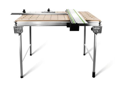
Fit the MFS routing template according to the instructions. In this case, the extension profile MFS VP 2000 is linked with two short MFS 200 profiles.
Adjust the circle routing insert so that it can move freely along the entire length of the groove. This is important to ensure that the circle routing insert can be moved quickly and precisely. To do this, position the circle routing insert on one corner and tighten the retaining screw on the MFS. Next, push the circle routing insert into the other corner, secure the MFS, tighten the retaining screw on the MFS and then check that the circle routing insert can move freely.
Insert the centring pin into the innermost groove of the MFS 200 and fix it in place.
Mark off the 8 mm hole for the centring pin on the centre line of the workpiece.
Drill an 8 mm hole into the panel using the cordless drill.
Clamp the cutter in the router up to the minimum clamping depth.
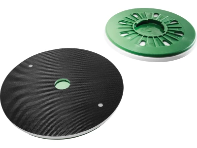
Install the copying ring in the router.
Set the maximum routing depth and fix it using the depth stop.
-
Tip: The MFS can be used to mark the contours of the segment arc

-
Adjusting the multi-routing template:
Install the MFS with the centring pin in the hole in the panel.
Loosen the circle routing insert. Insert the router into the circle routing insert and move to the mark on the outer radius.
Place the cutter on the workpiece surface.
Now align the cutting circle to the marking by rotating the cutter by hand. Repeat to rout the inner radius.Secure the circle routing insert by tightening the locking screw.
Fit the extractor to the router and connect the extractor hose.
Tip: The workpiece should be supported at three or four points so that the multifunction table and the substructure below it are not cut. This prevents the workpiece from tipping, producing an even arc.


Procedure
-
Clamp the workpiece to the multifunction table using the fastening clamps.
With the router set at the first routing depth (for multiplex, max. 5–8 mm per pass) make a plunge cut at the edge of the arc.
Slowly rout the contour for an even arc.
Now rout the full arc in a number of further steps.
After routing the outer radius, as described in "Setting up the MFS routing template", set the inner radius.
Rout the inner radius as described above.
-
Please note the routing direction:
If the circle or groove is routed out of solid material, the router, together with the template, can be moved either clockwise or anti-clockwise.
If subsequent routing is required for the segment arc, the outer radius must be routed anti-clockwise and the inner radius must be routed clockwise, to ensure that the cutter is guided in reverse direction.
After routing, the plunge-cut saw can be used to cut the segment arc to the right length.
-
Sawing procedure:
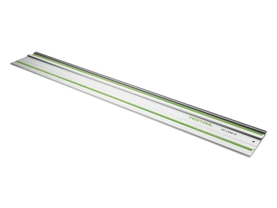
Align the guide rail to the marking and clamp.
Use the depth stop to set the sawing depth on the plunge-cut saw and select speed level 6.
Cut the arc at the marking.
Repeat on the other side as described.
Important: When plunge cutting, the saw blade must still not touch the workpiece to prevent kickback.


-
Our illustrated guides and work results are documented working steps that we have performed in practice. They are individual examples and do not guarantee or promise that users will obtain the same results. The results will depend on the user's experience and skill, as well as the material being used. Illustrated guides do not replace any Festool operating manuals and/or safety instructions. Liability for ensuring that the information, instructions and applications are free from content defects and defects of title, in particular with regard to the absence of defects, correctness, freedom from third party intellectual property rights and copyrights, completeness and fitness for purpose, is excluded. Claims for damages made by the user, regardless of their legal basis, are excluded. These liability exclusions are not applicable if the damage was intentional or caused by gross negligence, or in cases of statutory liability.
We cannot accept liability for damage resulting from defects.↑
