


Routing an ellipse with the router

Description
The following material is required:
- Multiplex cross plate, 15 mm thick
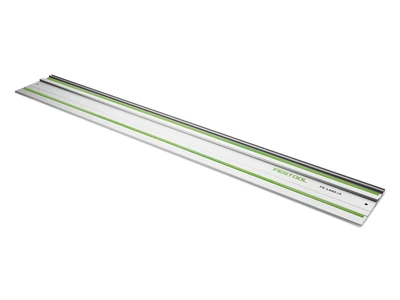
- 1 beech guide rail, 15 x 10 mm, 300 mm long
- Multiplex circle arm, 15 mm thick, 1000 x 120 mm
- 2 countersunk screws, M5 x 40 mm
- Double-sided adhesive tape
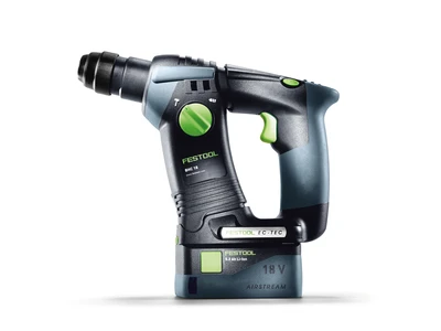
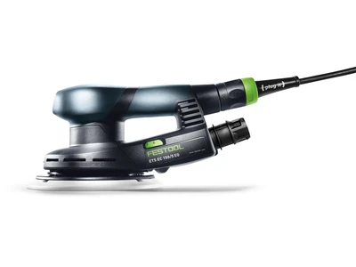
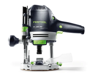
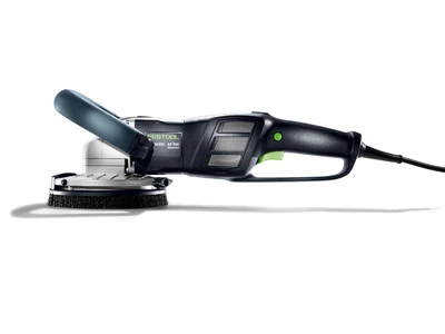
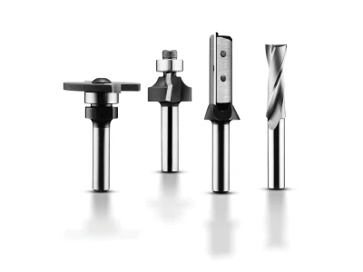
Tools/accessories

Alternative tools/accessories

Preparation/set-up
-
The following steps must be carried out before routing a trammel in wood:
To begin, you will need a 15 mm-thick multiplex panel that has been cut into a square. The size of the square depends on the size of the ellipse you want to produce. This panel will be used as the cross plate. Use a T-groove cutter to rout two 9 mm-deep and 15 mm-wide T-grooves into this multiplex panel. These grooves should intersect exactly in the middle of the panel. It is best to use a router with a guide rail; this will produce a precise, straight groove.

-
To begin with, calculate the size of the multiplex panel:
First, halve the width of the planned ellipse. In this illustrated example, an 800 mm-wide elliptical panel will be created. 800 mm/2 = 400 mm.
-
Next, halve the length of the ellipse. In this example, this is 1500 mm/2 = 750 mm.

-
Next, subtract the halved panel width (in this example, 400 mm) from the halved panel length (750 mm). This produces a halved circle distance of 350 mm in the cross plate.
Multiply this result (350 mm) by 2 and add a safety travel distance of 50 mm.
For the planned elliptical tabletop measuring 1500 mm x 800 mm, you would therefore require a cross plate measuring 750 x 750 mm.
-
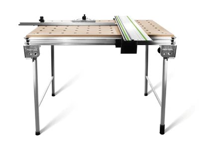
Equipping the machine for routing the ellipse: A T-groove cutter is fitted to the router and the guide rail adapter is fitted for working with the guide rail.


Procedure
-
The T-groove nut must later fit absolutely precisely in the T-groove without jamming. To achieve this, the guide rail used must be fastened to the multiplex panel using fastening clamps.
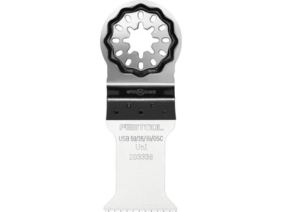
The T-groove cutter is 10.5 mm wide. As a result, it cannot finish routing the groove in one work step, which means that the router must be offset once on the guide rail.
-
So that both grooves are identical, use a 10 mm-wide spacer while routing. Place this template between the router base plate and the guide rail adapter.
The T-groove cutter has a (large) diameter of 10.5 mm. However, the T-groove needs to be 15 mm wide. A second spacer that is 4.5 mm wider than the first (i.e. 14.5 mm wide) is therefore needed.
By replacing the spacers in two work steps, as shown above, using a guide rail clamp in each case, the T-groove can be routed in the exact centre of the cross plate.
-
Now produce the 150 mm-long T-groove guide rails. To do this, create a small rebate on the left and right sides of the 10 x 15 mm beech rails. It is best to produce these rails on a router table using a groove cutter or rebating cutter. When producing these rails, ensure that they run smoothly in the T-groove that was routed previously. If you do not have access to a router table, you can also produce these rails using a semi-stationary circular saw.
Next, drill a 5 mm hole in the centre of the rails for the M5 countersunk screw.
The screwhead must be completely countersunk in the rail.
-
The circle arm is also made of 15 mm-thick multiplex and measures 1000 x 120; it will be the moving arm in the trammel.
First, saw off approx. 150 mm from the 1000 x 120 mm-long strip. Next, screw this 150 mm section onto the remaining strip at a 20 mm offset from below. This compensates for the height difference.
-
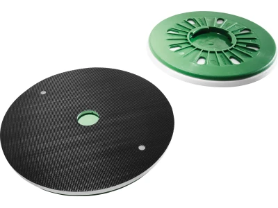
To hold the router on the circle arm quickly and easily, a copying ring should be added to the router. In this example, a 30 mm sleeve has been used as this is enclosed with most routers. Use a Forstner bit or cylinder bit to then drill a 30 mm guide hole for the copying ring into the multiplex panel.
The hole should be positioned 50 mm from the front of the circle arm and in the centre of the circle arm (120/2 = 60 mm).
-
Finally, drill the 5 mm holes for the two M5 countersunk screws (in the guide rails). The distance between these holes and the centre of the copying ring determines the outer dimension of the ellipse.
If you would like an adaptable solution, drill a number of holes at a spacing of 25 mm, as shown in the image. This allows you to adjust the trammel each time you use it.
Of course, you can alternatively drill just the two holes you need for the ellipse you are currently producing. The hole spacing is easy to calculate: For an elliptical tabletop measuring 1500 x 800 mm, a hole spacing of 750 and 400 mm is calculated first. Now, calculate half of the routing diameter (i.e. 6 mm for a cutter with a diameter of 12 mm) and add this to the above values. Therefore, hole 1 is positioned 756 mm and hole 2 is positioned 406 mm from the centre of the copying ring.
-
Now fasten the prepared trammel to the panel to be routed. To do this, first mark the central axes of the panel in pencil. Next, align the base plate of the trammel with these central axes and fasten it using either two small screws on the underside of the panel or using double-sided adhesive tape on the side of the panel which will visible. Only use adhesive tape that can be removed without leaving residue. If tape with too high an adhesive strength is used, this can damage the workpiece and base plate.

-
Next, push each of the guide rails into one of the dovetail grooves. The guide rails should have the 5 mm countersunk screws already inserted.

-
Next, insert the screws into the correct 5 mm holes on the circle arm. Secure the entire assembly using a washer and two nuts. Important: Do not tighten the screws too tightly. If they are tightened excessively, the circle arm will not be able to rotate above the guide rails. The use of lock nuts or stop nuts may be practical. These will prevent the entire assembly from loosening and thereby avoid inaccuracies when routing.

-
Routing the ellipse is then as easy as can be. The router can be guided easily and securely using the copying ring on the circle arm. This virtually eliminates the possibility of creating inaccuracies when routing. The picture also clearly shows the function of the stepped compass. It ensures that the router is supported and cannot tip over. However, this also means that the cutter in use requires a long blade in order to cut completely through the panel.
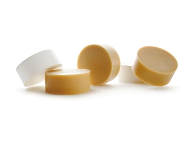
This device allows you to rout a perfect ellipse easily and quickly, without spending your time using complicated formulae for difficult calculations. Depending on the size of the ellipse, you may need to make a smaller or larger base plate for routing. The guide rails and the circle arm can be re-used with the new base plate. When routing, it is crucial to ensure that the guide rails run smoothly in the dovetail grooves on the base plate. If needed, lubricant or curd soap can be used to make this easier.
-
Tip: For any parents reading – if your cutter is already set up, it is easy to make a "mini" trammel for use with a pencil. The mechanism is fascinatingly simple and even little ones can have a go at drawing an ellipse!


-
Our illustrated guides and work results are documented working steps that we have performed in practice. They are individual examples and do not guarantee or promise that users will obtain the same results. The results will depend on the user's experience and skill, as well as the material being used. Illustrated guides do not replace any Festool operating manuals and/or safety instructions. Liability for ensuring that the information, instructions and applications are free from content defects and defects of title, in particular with regard to the absence of defects, correctness, freedom from third party intellectual property rights and copyrights, completeness and fitness for purpose, is excluded. Claims for damages made by the user, regardless of their legal basis, are excluded. These liability exclusions are not applicable if the damage was intentional or caused by gross negligence, or in cases of statutory liability.
We cannot accept liability for damage resulting from defects.↑
