


Longitudinal joints to partially replace or extend beams at the threshold or top plate

Description
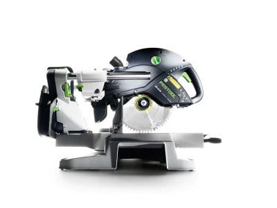
With the right tool, longitudinal joints can be used to connect beams. When it comes to partially replacing wood in old buildings, it goes without saying that the precise procedure for making longitudinal joints very much depends on the local conditions, space available and wood cross-sections. This guide presents the scenario of a renovation project. The guide explains precisely what steps are required to make a longitudinal joint, from cutting to cogging and fitting the threaded bolts. In the main, various portable circular saws are used.
Material list
- 12 x 20 cm wood
- Threaded rods or threaded bolts
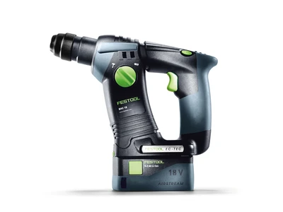
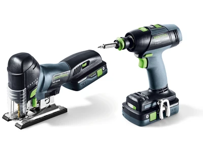
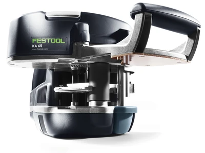
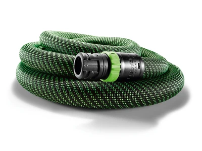
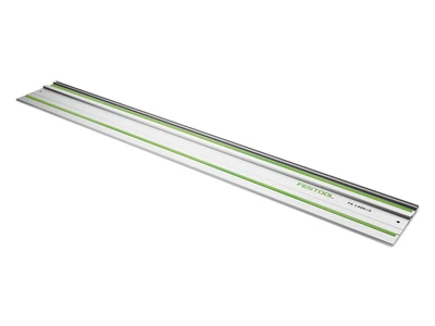
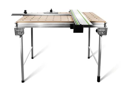
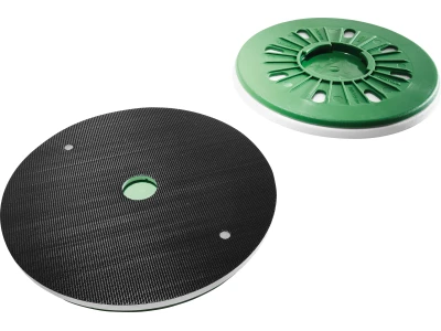
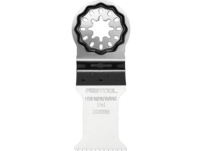
Tools/accessories


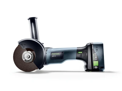
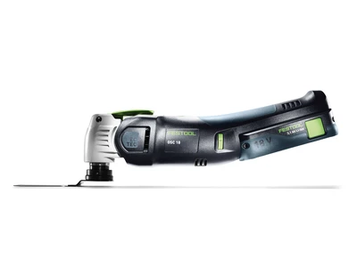
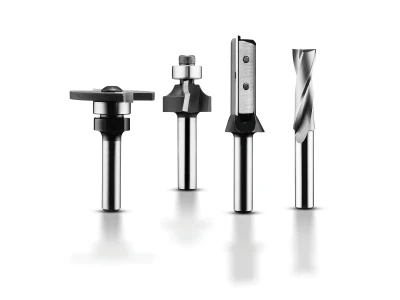
Alternative tools
Preparation/set-up
-
Marking wood
Before you can connect the beams with a longitudinal joint, the beams must first be marked. The design of the French scarf joint is based on the thickness of the wood. A length of three times the wood thickness was chosen for the scarf joint. The cogging depth was set at 3 cm.


Procedure
-
Fixing the guide rail to make a longitudinal joint
If the angle stop is aligned, it can be fixed with fastening clamps.

-
Cutting with the portable circular saw
The portable circular saw can now be used for cutting. Repeat the process for the counterpart.

-
Completing the longitudinal section
Finished section

-
Cogging
To cog a joint, you must first make incisions on the limit line. This is very easy with the portable circular saw when used in conjunction with the cross cutting guide rail. To do this, set the cutting depth accordingly, position it on the crack and make cuts.

-
Cogging
Making a cut on the central axis

-
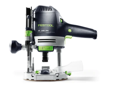
Fitting the adjustable groove cutter into the portable circular saw
The adjustable groove cutter can be used to quickly smooth the central area of the clogging. To do this, the saw blade must be removed and the adjustable groove cutter must be fitted in accordance with the operating instructions. In this example, a maximum routing width of 25 mm has been chosen.

-
Routing the cogging
After the routing depth has been adjusted, the cogging can now be routed in conjunction with the cross cutting guide rail. When the joints are visible at a later stage, it is recommended that you pretension a test piece of wood to ensure that the crack is minimal.

-
Completing the cogging
Finished cogging

-
Creation
The two parts can now be made.

-
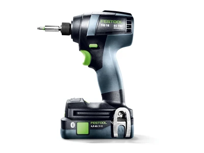
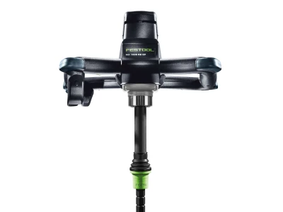
Use the drill stand to make a bore hole for the screw-bolt-joint
The necessary bore holes can be made using the clamped cordless drill in a carpentry drill stand.

-
Second drilling stage
A Forstner drill with a depth limiter is also used to drill the bore holes for the washers.

-
Fitting the threaded bolts
The threaded bolts can now be fitted and tightened.

-
Removing the markings
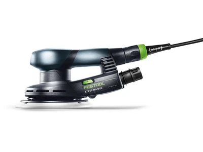
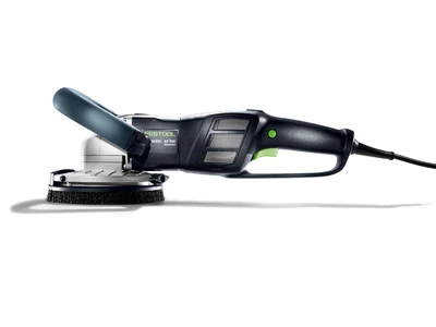
As an option, the wood and longitudinal joint machining areas may be sanded with a cordless sander to remove pencil markings.

-
Finished joint
The longitudinal joint provides a result which is attractive and robust for the beams.


-
Our illustrated guides and work results are documented working steps that we have performed in practice. They are individual examples and do not guarantee or promise that users will obtain the same results. The results will depend on the user's experience and skill, as well as the material being used. Illustrated guides do not replace any Festool operating manuals and/or safety instructions. Liability for ensuring that the information, instructions and applications are free from content defects and defects of title, in particular with regard to the absence of defects, correctness, freedom from third party intellectual property rights and copyrights, completeness and fitness for purpose, is excluded. Claims for damages made by the user, regardless of their legal basis, are excluded. These liability exclusions are not applicable if the damage was intentional or caused by gross negligence, or in cases of statutory liability.
We cannot accept liability for damage resulting from defects.↑
