


Building your own sawhorse with a dovetail joint

Description
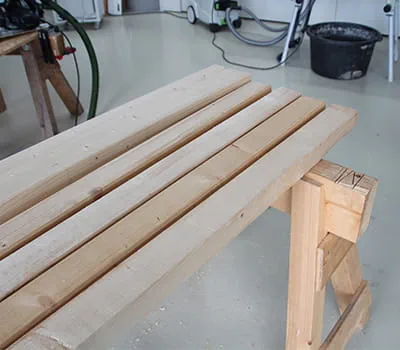
Sawhorses with protruding legs are extremely stable and can bear very heavy loads. However, when compared to other designs, they take up a considerable amount of space when transported. Its design with dovetail joints allows the sawhorse to be disassembled and transported without taking up much space, while maintaining its stability.
Material list
The following is required to make a pair of horses:
- Beams, 80 x 160 solid structural timber (KVH), 2 m long, one unit
- Legs, 60 x 80 solid structural timber (KVH), 2 m long, four units
- Wooden butt straps, 19 mm three-layer board, 120 x 300 mm, four units
- Screws, 5.0 x 50 mm, 16 units
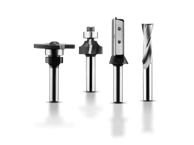
Tools/accessories


Preparation/set-up
-
Preparing the materials
The materials shown in this design plan will be enough for a pair of sawhorses.
-
Marking the beams
The sawhorses constructed in these instructions have a total length of 90 cm. A marking for the axis is made 20 cm from each end to indicate the position of the legs. When doing this, the two legs remain attached to make it easier and safer to clamp the individual parts.
-
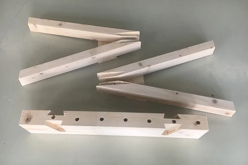
Marking the beams for dovetail milling
The legs shown here are at an angle of 12°. A template has been prepared here to make marking the beams easier.
An additional marking is made 35 mm from the crack so that the template can be positioned at a later time.
The template for dovetail milling is available from LignaTool.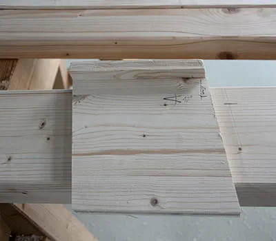
-
Marking the sawhorse legs
The end of the leg adjacent to the beam has an incline of 15°. The legs are marked accordingly for this purpose. A wedge with edges measuring 13 x 3.5 cm is marked.


Procedure
-
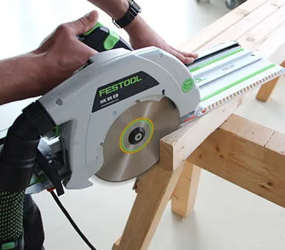
Cutting the sawhorse legs
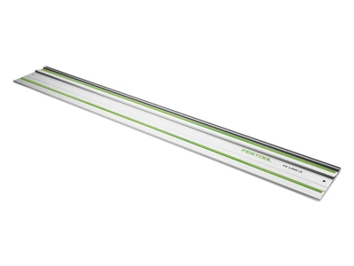
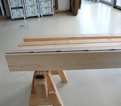
All of the legs (6 x 8 cm) are cut with the portable circular saw and the fitted cross cutting guide rail. As with the beams, two legs remain attached to each unit.
-
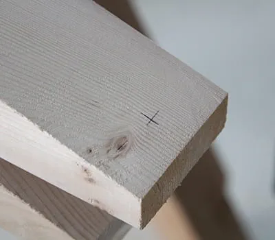
Make a mark for the dovetail joint tenons on the cutting area of the sawhorse legs
At the centre, 2 cm from the grinding face
-
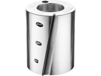
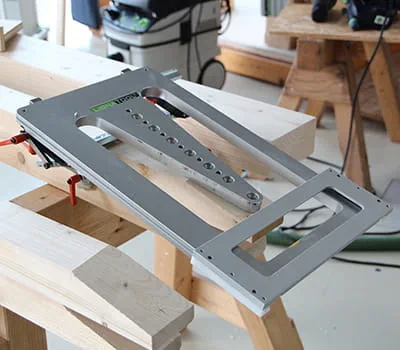
Positioning the template
The template is positioned and fixed at the mark. More detailed information about the LignaTool system can be found at: www.lignatool.at
-
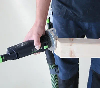
Adjusting the depth on the router
Position and fix the router on the material upper edge.
-
Turning the stepped stop to the lowest setting
The lock can be activated in this position at a later stage in order to couple the base plate with the milling unit.
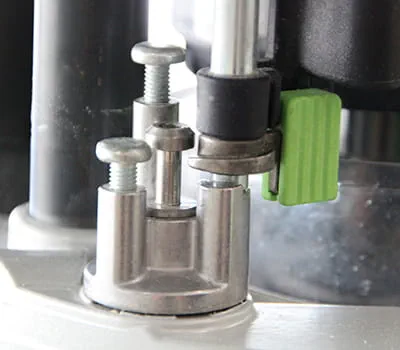
-
Set the depth stop indicator to zero.
-
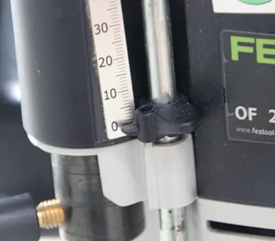
Setting the routing depth
Adjust the depth stop to 25 mm and fix the depth stop.
-
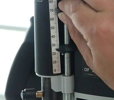
Adjusting the depth
Move the router to the set depth and activate the eccentric sander for coupling the depth stop and the stepped stop. Then open the routing depth clamp on the handle. The depth can now be conveniently set to the precise depth using the gauge and fine adjustment.
-
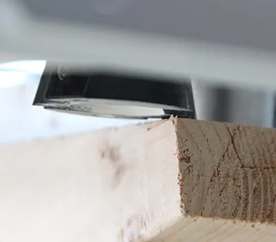
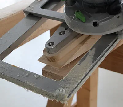
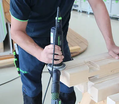
Milling the dovetail joint
Carry out the routing on all of the legs.
-
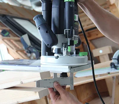
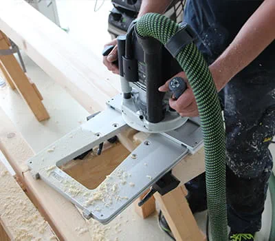
Positioning the template for routing the mortise on the beam
Align and fix the routing template.
-
Carrying out the routing on the beams
The routing is carried out with the depth already set.
-
Trimming the components
As already noted, it is recommended that you only trim the components to their end length after routing. The legs are now also trimmed at the centre. However, the end lengths of the legs will only be produced with precision at a later stage when they have been assembled.
-
Chamfering components
The cut components can now be chamfered and also sanded, where necessary.
-
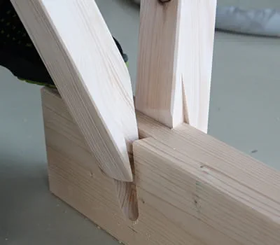
Inserting the legs
Insert the legs and use a hammer to press-fit them.
-
Position and mark the wooden butt straps
-
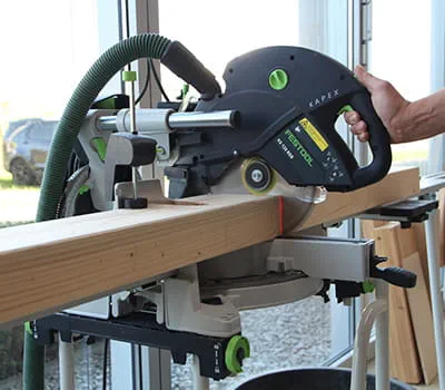
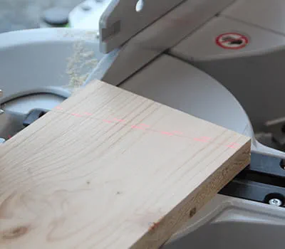
Cutting the wooden butt straps with the compound mitre saw
Align the boards with the cutting line laser and cut them
-
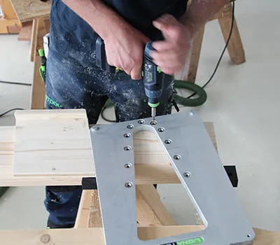
Pre-drilling the wooden butt straps
Pre-drill the screw positions with the drill countersink.
-
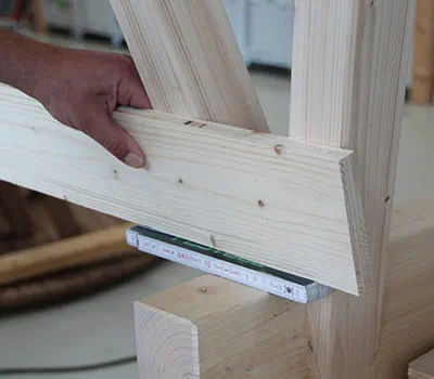
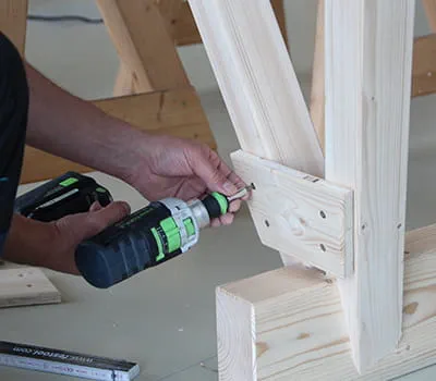
Assembling the wooden butt straps
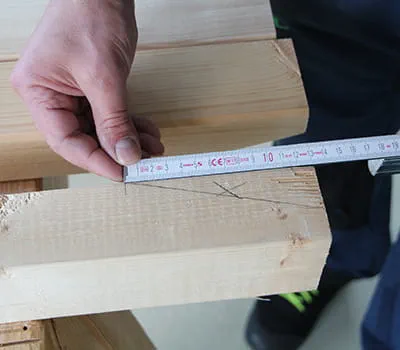
Ensure that the legs fit tightly in the joint. Important: The straps should be fitted at a distance from the beam (the width of a meter rule can be used for this purpose).
-
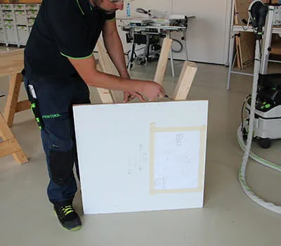
Marking sections of the legs
Mark the required height of the sawhorse on its legs with a board (in this example, 75 cm)
-
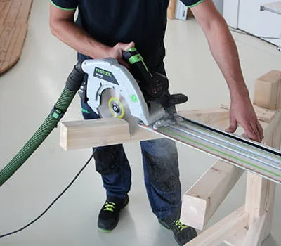
Shorten the legs using the portable circular saw and cross cutting guide rail
Set the portable circular saw to an inclination of 12°. Simply position it and make the cuts.
-
Chamfering the footprint
The cutting edges and subsequent footprints should also be machined with the edge router.
-
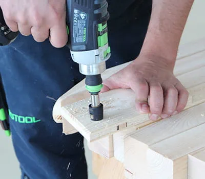
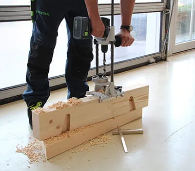
Tip: In addition, drill bore holes into the beams
Having additional 20 mm bore holes means that the MFT clamping system can be used. It is recommended that you drill continuous bore holes so that chips can fall through below.
-
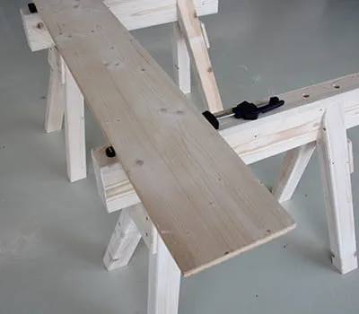
End results
Complete sawhorses with a clamped workpiece


-
Our illustrated guides and work results are documented working steps that we have performed in practice. They are individual examples and do not guarantee or promise that users will obtain the same results. The results will depend on the user's experience and skill, as well as the material being used. Illustrated guides do not replace any Festool operating manuals and/or safety instructions. Liability for ensuring that the information, instructions and applications are free from content defects and defects of title, in particular with regard to the absence of defects, correctness, freedom from third party intellectual property rights and copyrights, completeness and fitness for purpose, is excluded. Claims for damages made by the user, regardless of their legal basis, are excluded. These liability exclusions are not applicable if the damage was intentional or caused by gross negligence, or in cases of statutory liability.
We cannot accept liability for damage resulting from defects.↑
